|

|

|

|
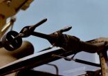
| Airspeed and Directional Sensor (AADS): The AADS is mounted on a boom to the right side of the airframe between the pilot and gunner stations. The purpose is to measure local airflow pitot and static pressure, the angle of the airflow relative to the helicopter, and the air temperature. The probe can swivel 360 degrees in pitch and 60 degrees plus or minus in yaw, accurately senses impact and static pressure up to 250 knots forward, 50 knots aft, 50 knots left and 50 knots right. The probe information is also used for rocket and automatic gun operations. A 115 VAC heater is contained within the probe which can be activated by the pilot during inclement weather. |

AADS |
Landing light: Their are two types of landing lights incorporated on the AH-1. The first is a skid landing light which is shown in the picture and the other is a retractable pilot controlled searchlight.
Skid landing light
Searchlight
Synchronized Elevator
The synchronized elevator is located near the aft end of the tailboom and is connected by
control tubes, idlers, and bellcranks to the fore and aft cyclic system. The control
linkage is attached to the aft horn of the swashplate which causes the angle of attack of
the elevator to change as it moves in conjunction with fore and aft cyclic stick movement
only.
Because of the peculiar operation of the overcenter bellcrank in the system, the elevator's angle of attack is changed in an unconventional manner, dependent upon the position of the cyclic stick in the cockpit. The elevator is at maximum nose down when the cyclic stick is centered or in the normal flight position. By being in the maximum nose down position during forward flight the elevator tends to keep the nose of the helicopter up, thereby, increasing the CG range and improving the controllability
Tail Rotor:
The tail rotor is a two-bladed, semirigid rotor system that is underslung and delta hinged
with a flex beam employing 1 degree preconing. The purpose of the tail rotor is to provide
thrust for antitorque control of the helicopter.
Tail Skid:
A tubular steel tail skid is installed on the aft end of the tailboom. The skid
act as a warning to the pilot upon an inadvertent tail-low landing and aids to prevent
tail rotor from damage.
Telescopic Sight Unit (TSU):
The TOW system has a stabilized telescopic sight with low (2-power) magnification and
(13-power ) magnification positions. The gunner can select either power by moving the MAG
switch on the left handgrip of the TSU.

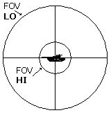
When the gunner selects the LO position, he has a 28-degree field of view (FOV). By
applying pressure to the sight control, the gunner can move the TSU. The bucket containing
the optics can be moved in azimuth 110 degrees to the left and right of the helicopter
centerline, 30 degrees in elevation, and 60 degrees in depression. The sight slews at a
rate of 73 degrees per second in azimuth and 45 degrees per second in elevation for low
magnification; it slews at a rate of 4.4 degrees per second in azimuth and 3 degrees per
second in elevation in high magnification. When the sight is operating in the LO position,
a circle is displayed on the sight reticle. This circle represents the field of view for
high magnification. With it the gunner determines when he can move to high magnification
without losing contact with the target. He also uses it to see in which direction and how
far he must search to acquire the target after switching to the HI position.

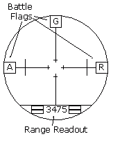
When the sight is operating in the HI position, the gunner has a 4.6-degree FOV. The reticle image displayed in the TSU consists of an outer circle with a vertical and a horizontal cross hair. Vertical marks that aid the gunner in estimating range to the target are positioned along the horizontal cross hair on high magnification only. The distance between the outer vertical marks is 10 mils; the inner marks, 2 mils. At the center of the sight reticle is an opening that is 0.4 mils wide. This area displace a 54-inch square at the maximum range (3,750 meters) of the missile. This is the aiming point for the gunner when he is sighting on targets.
Wire Strike Protection System:
![]()
The wire strike protection system consists of three cutter assemblies, a windshield channel and a nose deflector. An upper cutter assembly is mounted on top of the pilot station, forward of the ADF loop antenna. A chin cutter assembly is mounted under the nose, just forward of the gunner station. A lower cutter assembly is mounted on the forward fuselage, under the ammunition compartment. The wire strike protection system is designed to protect the helicopter from wire obstructions at low levels of flight.
|
|
|
|
| Updated: 12 January 2008 | Born on 25 September 1998 |